
Onboard and Install a Digital Matter G70 Device
This article explains how to onboard and install a Digital Matter G70 device for use with Virtual Superintendent.
The G70 is a compact and robust GPS tracking device designed for demanding environments. It supports multiple inputs and outputs and can be mounted on machines to provide accurate tracking of fleet movement and material activity when used with the SafeSite mobile app and Virtual Superintendent.
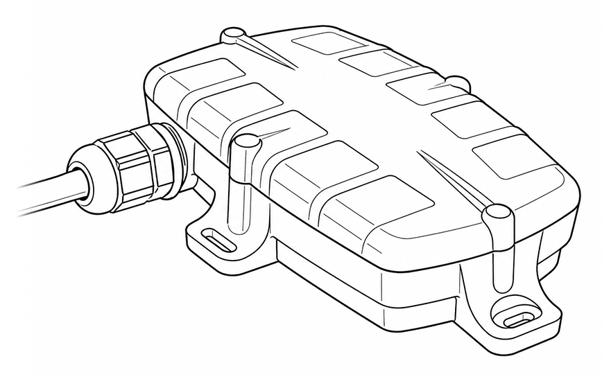
You can download the detailed G70 datasheet from the Digital Matter website here.
In this article
- Permissions
- Before you begin
- Install the SafeSite app
- Onboard a G70 device
- Install a G70 device on a machine
- Insert SIM card and connect battery
- G70 wire definition
- Connect the G70 device to load or dump switches
- OEM installer device check
- Using a relay for alternator power
- Other important information
Permissions
To onboard a G70 device through the SafeSite app, you must have the following SafeSite permissions enabled:
- Superuser
Before You Begin
Before installing a G70 device on a machine, you must onboard it. Onboarding links the device to a specific machine so it can transmit data correctly to Virtual Superintendent.
Onboarding is completed using the SafeSite mobile app. To complete the onboarding process:
- Install the SafeSite app on your mobile device.
- Sign in with a user account that has permission to onboard devices.
If you have not yet installed SafeSite app, install it before starting the G70 onboarding process.
Install the SafeSite App
To install the SafeSIte mobile app:
- Find the Cloudscape SafeSite app page in the App Store (iOS) or the Google Play store (Android) then download and install the app.
- Open the app on your device.
- Tap Scan QR Code and grant the app permission to use your device camera.
- Scan your unique registration QR Code. This code should be provided to you by your supervisor or head office.
- Review the details shown on screen.
- Tap Next, then tap Sign on to start using the SafeSite app.
Onboard a G70 Device
You must onboard a G70 device before installing it on a machine. Onboarding links the device to a specific machine so it can transmit data to Virtual Superintendent.
To onboard the device:
- Open the SafeSite app and sign in.
-
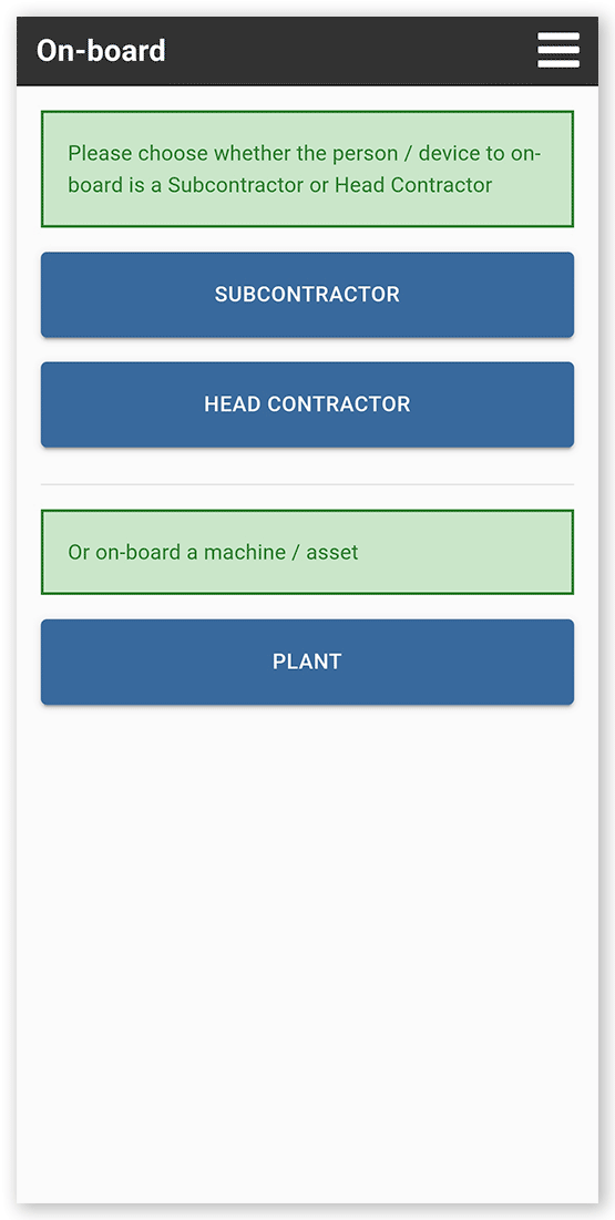
Open the menu and tap On‑board. The On-board screen opens.
 Click or tap to expand image
 -
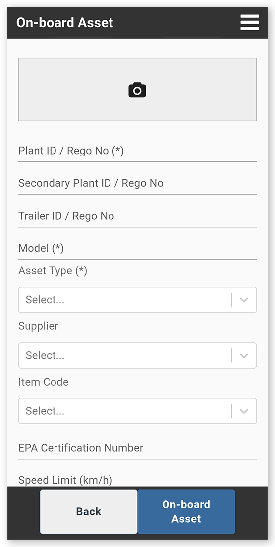
Tap Plant. The On-board Asset screen opens.
 Click or tap to expand image
 - Enter the machine details and take a photo of the machine.
-
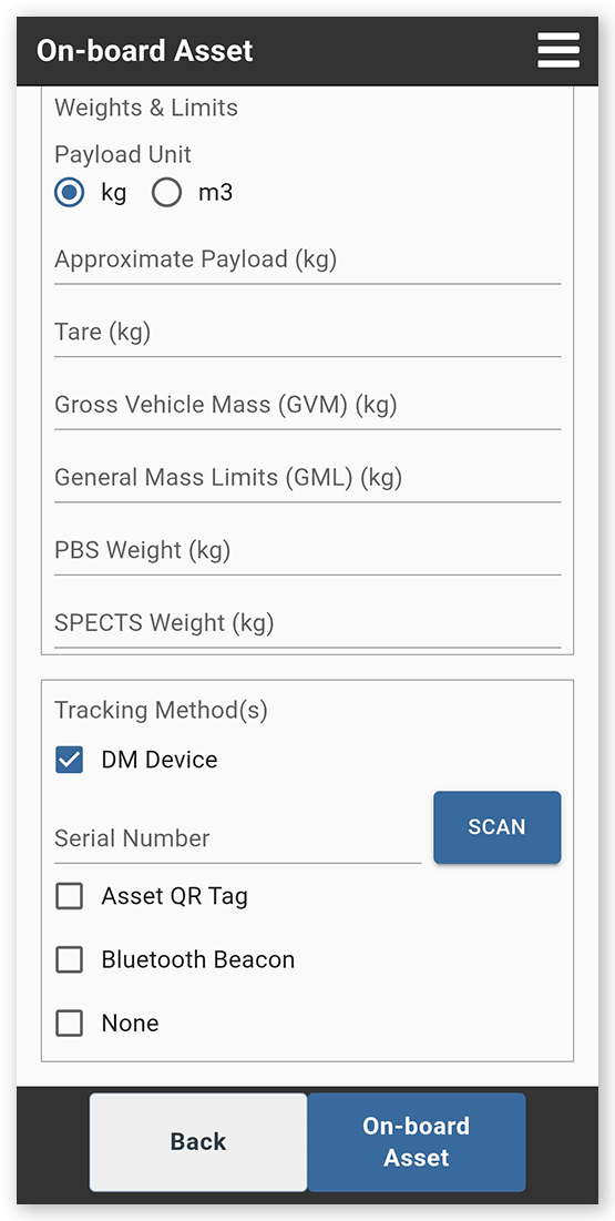
Scroll to the Tracking Methods section at the bottom of the page and select DM Device. A Serial Number field opens.
 Click or tap to expand image
 - Record the G70 device's serial number in the Serial Number field. You can either tap Scan and point the camera at the barcode on the back of the G70 device, or manually enter the serial number.
- Review the details and tap On‑board Asset to complete onboarding.
Important
- Enter the serial number, not the IMEI number.
- The serial number is a 6‑character code printed on the back of the device.
Install a G70 Device on a Machine
After a G70 device is onboarded, it is ready to be installed on a machine.
G70 devices are designed to operate while the machine is running and draw power from 12 V or 24 V systems. Devices are typically mounted under the dashboard. Avoid mounting the device in areas surrounded by metal, as this can interfere with the GPS signal.
See the Digital Matter Support page for more information.
Note: Before installing the device on a machine, you must insert the SIM card and connect the internal battery. These steps are required to ensure the G70 powers on and communicates correctly. The G70 does not operate unless both the SIM card is installed and the battery is connected.
Insert SIM Card and Connect Battery
Before installing a G70 device on a machine, insert a SIM card and connect the battery.
Each G70 package includes:
- The G70 device in its bottom housing
- A top cover with four housing screws
- An internal backup battery (1100 mAh LiPo, located under the PCB)
- A 10‑wire harness (1 m, 3.3 feet)
- Spare label (with serial number)
The device ships without the top cover attached so you can insert the SIM card and connect the battery. Insert the SIM card before connecting the battery.
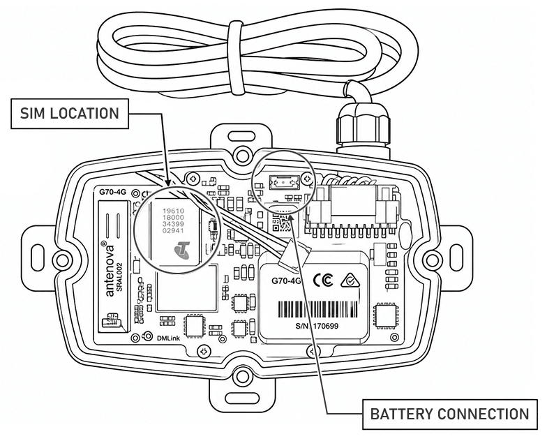
Insert the SIM card
The SIM card holder is located on top of the green circuit board and accepts a Micro (3FF) SIM.
To insert the card:
- Slide the SIM holder sideways to release.
- Tilt the holder upward.
- Place the SIM card so it makes contact with the SIM contacts on the PCB. Check that the SIM corner notch is correctly oriented before closing.
- Close the SIM holder and slide it sideways, locking it back into place.
Connect the battery
Connect the battery to the white three pin battery connector on the PCB.
Once the SIM card is inserted and the battery is connected, place the top cover on the device and secure it using the four housing screws provided. Ensure the device is sealed correctly to reduce exposure to water.
Note: The G70 includes an internal backup battery to maintain operation in the event of power loss or tampering. See here for information about estimated battery backup life.
G70 Wire Definition
Common wiring connections
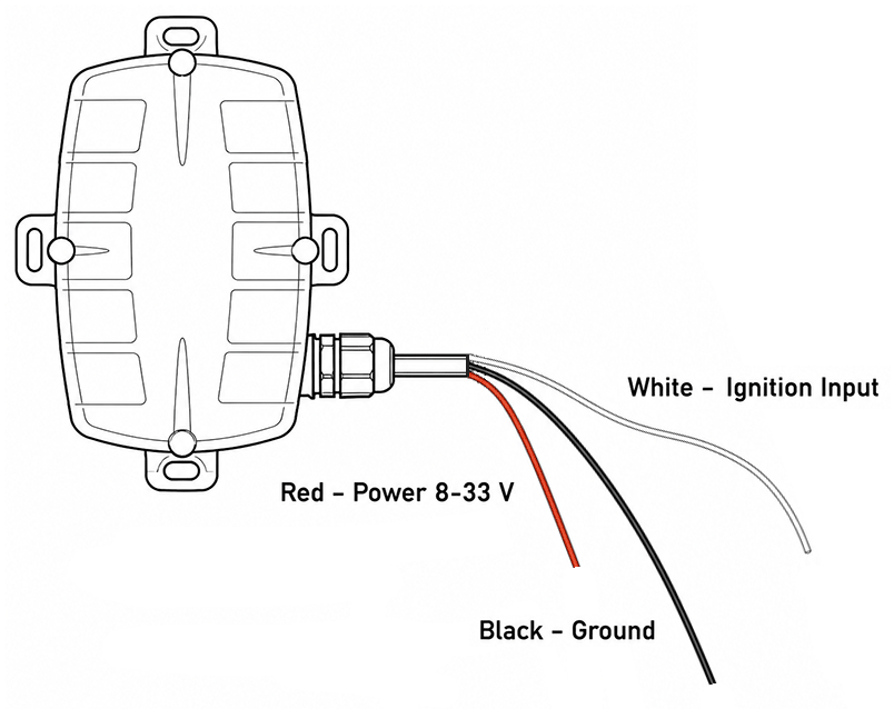
Typically the install uses the following three wires:
| Wire | Color | Pin | Connection |
|
Voltage in
|
Red | Pin 1 | Connect to vehicle battery (8-33 V) |
|
Ground
|
Black | Pin 2 (or any black wire) | Connect to chassis ground |
|
Ignition input
|
White | Pin 3 |
Connect to ignition source |
Important ignition wiring requirements
You must ensure that no power is present on the ignition wire when the machine is turned off. If power is always present, the machine cannot sign on correctly and will not be detected by Virtual Superintendent.
Machines without an ignition wire
If the machine does not have a dedicated ignition wire:
- Connect both Voltage in (Pin 1) and Ignition input (Pin 3) together.
- Connect them to the machine’s power supply.
Important:
The power supply must not be live when the machine is turned off or isolated. If power is always present, the machine cannot sign on and will not be detected by Virtual Superintendent.
G70 device wire definition
The following table includes an overview of all G70 pin connections:
| Pin | Color | Function |
| 1 | Red | +V.IN / BATT (8-33 V) |
| 2 | Black | GROUND |
| 3 | White | IGNITION INPUT 'ON' AT >2.2 V |
| 4 | Blue | DIGITAL INPUT 1 |
| 5 | Orange* | DIGITAL INPUT 2 |
| 6 | Brown | DRIVER ID 1 (iBUTTON DATA / WIEGAND D1 / TTL RX) |
| 7 | Purple | DRIVER ID 2 (DIGITAL INPUT 3 / WIEGAND D0 / TTL RX) |
| 8 | Green | SWITCHED GROUND |
| 9 | Yellow | ANALOG INPUT |
| 10 | Grey | GROUND |
*Some early devices used a pink wire for pin 5. The current standard is orange.
Connect the G70 Device to Load or Dump Switches
Load events
To record load events:
- Connect Pin 5 (Digital Input 2, orange or pink wire) to a loading switch or signal that increases voltage when the machine is loading.
- A voltage change from less than 2 volts to greater than 2 volts on Pin 5 triggers a load event.
Dump events
To record dump events:
- Connect Pin 4 (Digital Input 1, blue wire) to a dumping switch or signal that increases voltage when the machine is dumping.
- A voltage change from less than 2 volts to greater than 2 volts on Pin 4 triggers a dump event.
OEM Installer Device Check
Check device status
To check the device status:
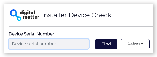
- Open the OEM Installer Device Check page.
- Type the G70 device serial number in the Device Serial Number field.
- Click Find. The device status is displayed.
What to verify
After locating the device, confirm the following:
- The correct Device Type is shown.
- The device has connected recently under Last Communication.
- Last Commit Time matches or closely follows the Last Communication time. A commit indicates a successful data upload. If the device has not committed recently, reported data may be out of date.
- The device has a recent Last GPS Update time.
- The Battery Level is not low (4.2 V is fully charged, low charge is below 3.7 V).
- The External Power level matches expectations. Check this value with ignition on and with ignition off. Refresh the page after changing ignition state to confirm results.
- The ignition status toggles correctly when the vehicle ignition is turned on and off (beside Ignition under Digital Inputs).
Using a Relay for Alternator Power
If you source power directly from an alternator and the G70 device does not detect the signal, using a relay can resolve the issue.
The relay is triggered by the alternator output and supplies a separate voltage to the G70. When the relay closes, the G70 detects the voltage and records ignition status correctly.
See the Install a Digital Matter Device Using a Relay help article for more information.
Other Important Information
Additional important information to be aware of:
- The G70 includes an internal self‑resetting thermal fuse, so external fuses are not required.
- The device uses internal GPS and cellular antennas, so no external antennas are required, making installation simpler.
- G70 devices perform reliably in common mounting locations, such as under the dashboard or under a trailer. In most cases, the most convenient installation location is suitable. For best performance, choose a location where the device has a clear 180‑degree view of the sky when possible.
- It is recommended to conceal the device where practical to reduce the risk of damage.
After the G70 device is onboarded using the SafeSite app, installed on the machine, connected to the internal battery, and fitted with a SIM card, it begins reporting data automatically.
See the Digital Matter Knowledge Base for more information.
Once power is supplied (when the machine is turned on) the device starts transmitting data to Virtual Superintendent. No additional configuration is required.